Contact
 Andy's Parts Smarts
 Cart
Cart

Replacing Universal Joints
Resources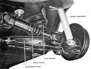 |
This diagram was taken out the Datsun 1600/510 workshop manual. I have made a PDF document of the 'Rear Suspension - Sedan Specifications' section of this book, its pretty large but well worth reading if you don't have access to your own manual. Download it HERE (right click and 'save target as') |
|
 This diagram was taken from a document I found on the internet about different types of uni joints - to find out what it had to say about the type used in your datto - please click
 Depending on what diff you are running, universal joints are often seen to be the weak point in a driveline. The standard datto 1600 rear end with R160 diff has 4 on the half shafts (one on each end) and then 2 on the tailshaft. If you are experiencing a 'clunking' noise and sensation on taking off and changing gears, then it is worth investigating the rear end to see if the uni's are to blame. To do this simply jack up the back of the car (placing blocks in front of the front tyres to prevent the car from rolling) and grab the half-shafts and try to rotate them back and forth quickly. If there is any play in the shaft (ie. the middle part of the shaft moves and the ends don't) then the universal joint is probably stuffed, and will need replacing.
Items needed
- jack, car stands and blocks
- new uni joints (about $50 from Repco)
- a couple of biggish nuts (about 15mm diameter)
- a decent heavy duty bench vice
- WD40, RP7 or other brand of lubricant
Tools needed
- wheel brace
- basic toolkit inc. 2x12mm spanners
- large round file
- pointy nosed pliers
- big hammer
- grease gun
Procedure
 To
remove the half-shaft, make sure the back of the car is securely jacked up,
preferably on car stands, then remove the wheels. Unbolt the end of the shock
(1x12mm nut) and let it swing free, then undo the 4 bolts that hold the end
of the half shaft (the yoke hub) in place. Using 2x12mm open ended spanners
against each other is the best way to do this. There are also 4 similar bolts
that hold the other end of the half shaft onto the diff, undo these to let the
entire shaft come off freely.
To
remove the half-shaft, make sure the back of the car is securely jacked up,
preferably on car stands, then remove the wheels. Unbolt the end of the shock
(1x12mm nut) and let it swing free, then undo the 4 bolts that hold the end
of the half shaft (the yoke hub) in place. Using 2x12mm open ended spanners
against each other is the best way to do this. There are also 4 similar bolts
that hold the other end of the half shaft onto the diff, undo these to let the
entire shaft come off freely.
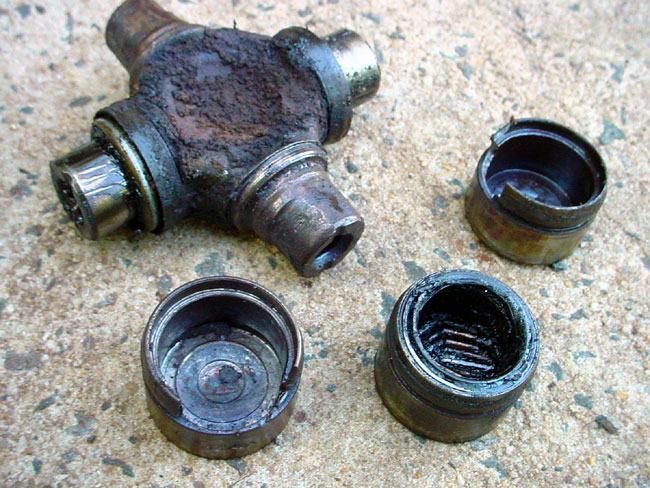
Next comes the 'fun' part - getting the old uni joint out of the end of the half shaft. There are clips that hold the joint in place so try and manouvre these out first, you may need to spray the area with some WD40 to clean and loosen the components first. If you can't get the clips out, hold the end of the half shaft on the bench and hit the floating yoke hub with a big hammer until it starts to come out; then try and remove the clip again as it should be easier now. Once the clips are gone it's a simple matter of bashing the crap out of the old uni joint until it comes out. Alternately put the joint in the vice and put a big nut on one end of the uni and just squeeze. Sounds a bit obscure I know but once its there in front of you its pretty easy to work out.
 |
 |
 |
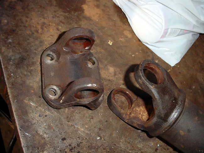 |
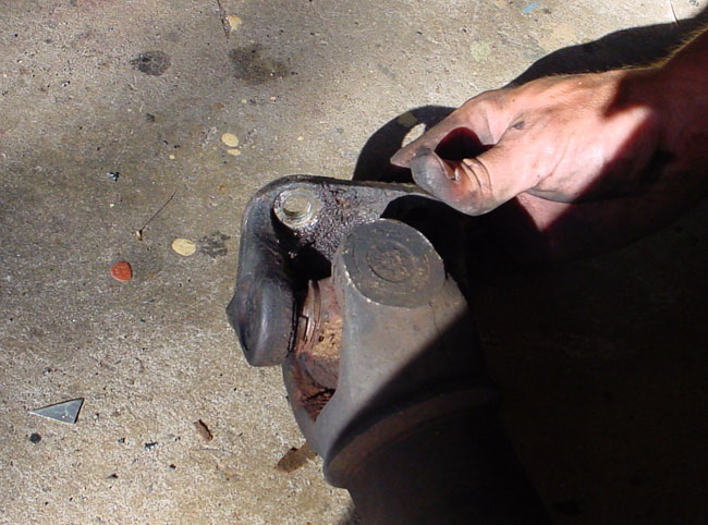
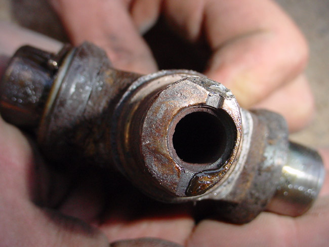
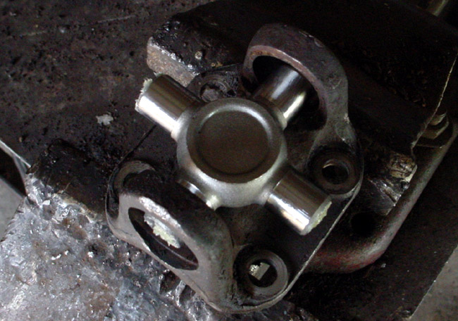
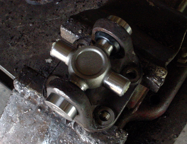
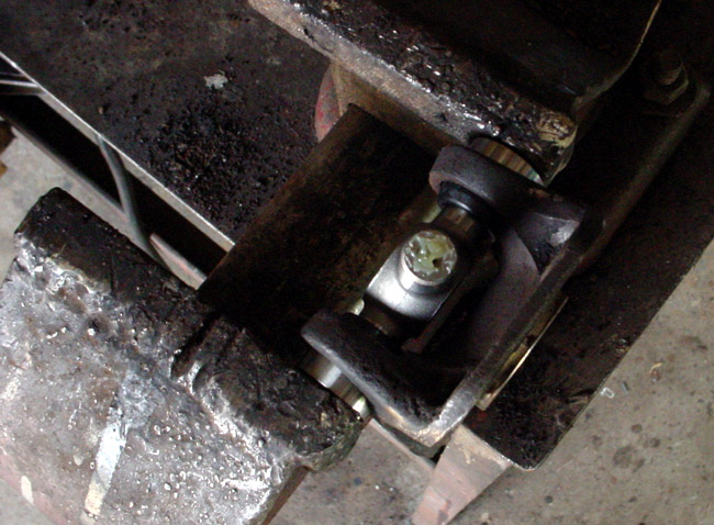
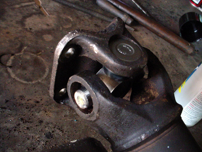
| The old uni joint in place at the end of the half shaft. | The bearing caps with munched or sometimes non-existant roller bearings. | The end of the cross piece (usually perfectly round) had been worn away by lack of bearings and mass amounts of friction. | This is what the end of the half-shaft should look like with the old uni joint removed. |
 |
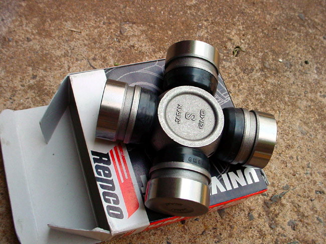
Once the old universal joint is out, file the edges of the holes on the yoke arms to make sure there are no sharp bits to damage your new uni's, and to make sure they will slide in easily. The new universal should look like this one, plus 4 clips and a grease nipple that are not visible in this photograph. A hint to those who are ordering them from a place like Repco - make sure you specify HALF SHAFT or DRIVESHAFT universal, because most employees automatically assume you are after a tailshaft uni, as they may be unaware that 1600's have independent rear suspension. The price difference is quite substantial - I was quoted $22 for a tailshaft uni by accident, then arrived at the store to find out the ones that I wanted were actually $58! I managed to talk them down to $45 though so that was ok. ;) |
 |
|
 |
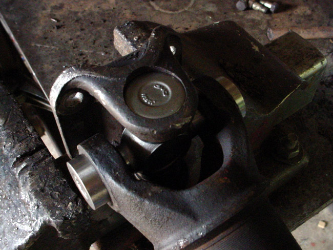
Step 1Slide the trunnion bearings off the end of the cross pieces and put them aside. Place the end part of the half shaft on the bench and put the yoke hub and cross piece in position. |
 |
Step 2Slide 2 of the trunnion bearings onto the ends of the cross piece, they should sit firmly in place. Be careful not to disturb the roller bearings inside. |
 |
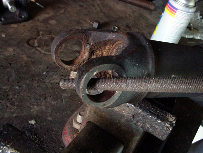
Step 3Put the uni in the vice with only the trunnion bearings in contact with it as shown. Slowly tighten the vice - the bearings should pull in and slide onto the cross piece. |
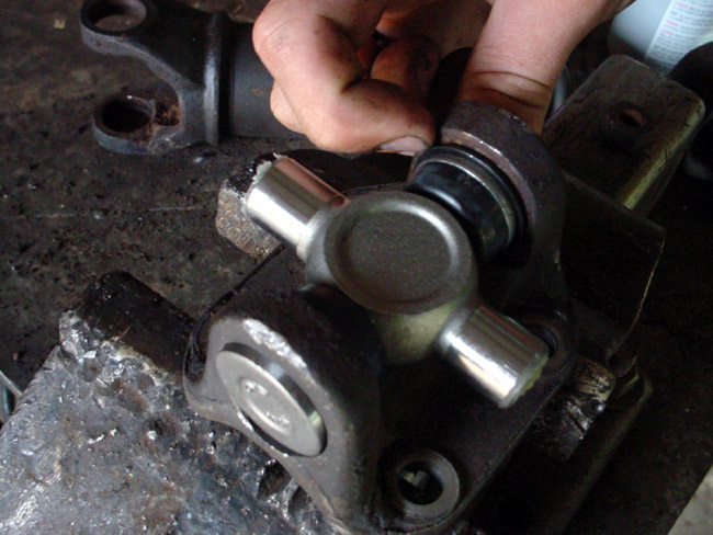 |
Step 4This is what the joint should look like after the bearings have been pushed on. The sir-clip on the far side has been clipped on and is pretty much in the correct position, you can just see it at the end of Andrew's finger. The bearing on the near side is not completely lined up yet; it needs to be pushed in that little bit further soit sits flush with the yoke arm. |
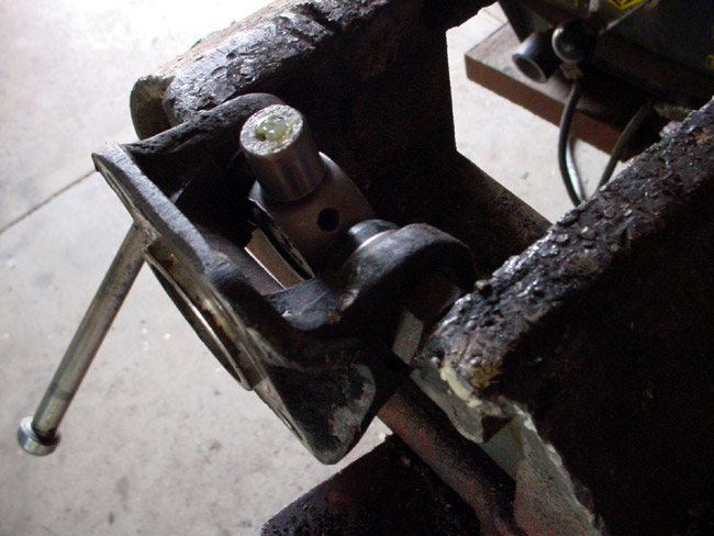 |
Step 5We can do this by putting the joint in the vice again but this time using a large nut (a little bit smaller than the end of the bearing) placed next to the end of the bearing, so when the vice squeezes them on the yoke arm, it doesn't get in the way.The remaining sir-clip can then be clipped on just inside the yoke arm - you will see a groove for it to sit in (also have a look at the previous photo). Use pointy nose pliers and a flathead screwdriver to make sure both clips are secure. |
 |
Step 6With one side of the joint completed, now get the main part of the half shaft and position the cross piece inside the second yoke arm. |
 |
Step 7Follow through steps 2-5 to fit the bearings onto the end of the cross piece. Make sure ALL 4 clips are in the right position and as far in as they will go!! Failure to do this may cause the bearings to work their way off the cross piece. |
 |
Step 8Lastly, screw in the grease nipple and fill 'er up! The joint is now complete and the half shaft ready to bolt back on. Happy (and safe!) motoring. :D |